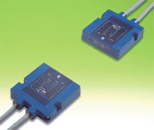
SOT-NP16 Series
Feature
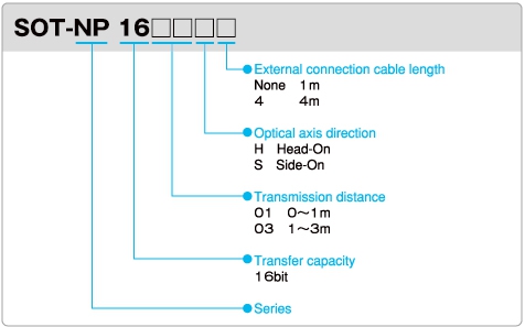
Model No. Descriptions
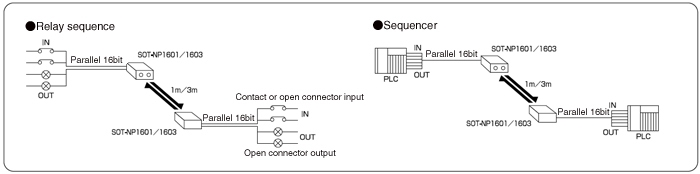
Sample System Configuration
Specifications
|
Model
|
SOT-NP1601H
|
SOT-NP1601S
|
SOT-1603H
|
SOT-1603S
|
|
Optical axis direction
|
Head-On
|
Side-On
|
Head-On
|
Side-On
|
|
Rated voltage
|
DC24V 10% or less ripple
|
|||
|
Operating voltage
|
DC18 – 30V Ripple
|
|||
|
Current consumption
|
100mA MAX
|
|||
|
Transfer distance
|
0 to 1m (with light intensity control knob set to MAX)
|
0 to 3m (with light intensity control knob set to MAX)
|
||
|
Emitting derection
|
30 degrees or more (at 1m distance)
|
5 degrees or more (at 3m distance)
|
||
|
No. of transfer bits
|
16 input bits and 16 output bits
|
|||
|
Transfer method
|
Semi-dual bi-directional or uni-directional
|
|||
|
Detection method
|
Continuous monitoring of bit status changes
|
|||
|
Transfer time
|
20ms max. (in M/S mode) or 30ms max. (in X mode)
|
|||
|
Sender element
|
Near infrared light emitting diode
|
|||
|
Receiver element
|
Photo-transistor
|
|||
|
Modulation method
|
Pulse width modulation
|
|||
|
Input date points
|
16 points
|
|||
|
Input style : Photo-coupler insulation (sink input)
Input signal : Contact or open collector Input voltage : 10 to 30 VDC (as measured between EXT+V and IN wires) Input current : 4±0.5mA (at 24 VDC) Residual voltage should be 2V or less with input current on and leaked current should bi 0.5mA or less with input current off. See 7-1 “Input circuit”. |
||||
|
Input date points
|
16 points
|
|||
|
Output style : Open collector output with non-insulated NPN transistor (sink output)
Applied voltage : 4.5 to 30 VDC Applied current : 100mA/output max. Residual voltage should be 1.5V or less with output current on and total applied current should be 500mA or less. See 7-2 “Output circuit”. |
||||
|
Indicators
|
POW: Lights up (red) when power is on
CTL/TCD: Lights up (red) when CTL input is on/lighted (green) when TCD input is on DT/RCV: Lights up (red) during successful data reception/lighted (green) during stable optical reception IN: Lights up (red) when data input is on OUT: Lights up (green) when data output is on |
|||
|
Connection
|
With attached 1-m cable (standard)
18C × 0.14mm2 (AWG26) 26C × 0.14mm2 (AWG26) |
|||
|
Ambient operating temperature
|
-20 – +50°C No freezing temperatures allowed.
|
|||
|
Ambient operating humidity
|
40 – 85% RH No condensation allowed.
|
|||
|
Ambient operating illumination
|
4,000lx or less for incandescent and fluorescent lamps
No externally disturbed light shall directly enter the receiver. |
|||
|
Vibration resistance
|
10 to 55Hz in frequency, 1.5mm in complex amplitude and 5minutes for sweep
20 cycles in each of X, Y and Z directions |
|||
|
Shock resistance
|
500m/s2, 20 cycles in each of X, Y and Z directions
|
|||
|
Enclosure rating
|
IP64
|
|||
|
Outside dimensions
|
90mm (W) × 90mm (D) × 20mm (H)
|
|||