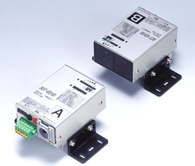
SOT-EQ(2.5Mbps)Series
Feature
The SOT-ES/EQ Series implements Ethernet backbone communications. It greatly improves the degree of freedom of network systems, with a wireless data transfer rate of 10 Mbps.
Connects wirelessly to Ethernet via infrared, enabling high-volume communication without loss of quality.
The SOT-EQ series (2.5 Mbps) has been added to the SOT-ES series (10Mbps), greatly improving cost performance.
The SOT-EQ series allows the carrier frequency to be changed via a DIP switch, enabling two-way communication
on the same track or in parallel without interference.
In the case of a conveyance control system, the cars and ground system can be connected to the same network,
enabling remote monitoring. A programmable control system can be used on the same network to greatly improve maintainability, by enabling program verification and modification on the mobile unit, in addition to normal data communications.
Unlike radio-wave communication, stable throughput is possible with communication between optical transmission systems. Optical communication is also more secure.
Each device can check the reception level of the other.
Specification
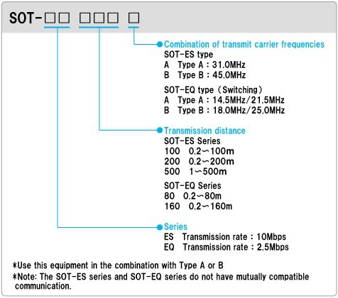
Model No. Descriptions

Sample System Configuration
FA-LAN System Configuration

Sample FL-net (OPCN-2) open net system configuration

Specifications (SOT-ES series)
|
Model
|
SOT-ES100A/B
|
SOT-ES200A/B
|
SOT-ES500A/B
|
|
Environment
|
IEEE802.3(Ethernet)
|
||
|
Transmission rate
|
10Mbps
|
||
|
Power voltage
|
Rated voltage : 24VDC (SOT-ES500 : 100V AC 50/60Hz)
Power ripples : 10% or less Voltage : 18-30VDC Peak voltage including ripples: Within 30V |
||
|
Current consumption
|
Less than 150mA (at 24VDC input)
SOT-ES500 : Power consumption 10VA or less |
||
|
Interface
|
10BASE-T(Auto negotiation, AutoMDIX compatible)
|
||
|
Transmission method
|
Full-duplex, bi-directional
|
||
|
Communication control method
|
Bit forward
|
||
|
Connected to:
|
Network card or switching hub
|
||
|
Transmission distance
|
0.2 -100m
|
0.2 -200m
|
1 -500m
|
|
Directivity
|
1.2 degrees
|
1 degrees
|
1 degrees
|
|
Modulation method
|
FSK
|
||
|
Lighting element
|
Near infrared light emitting diode(light emitting wavelength 870nm)
|
||
|
Receiving element
|
Photodiodes
|
||
|
Auxiliary output
|
DL: “ON” when communication is permitted |
||
|
Connection
|
For signal: RJ-45 modular jack
Up to category 3 or more twist pair cable 100m Automatic switching between straight/crossing cables by means of AutoMDIX For power/aux. output: 5-polar connector terminal block (Phoenix MSTB2.5/5-GF-5.08) |
||
|
Indicator
|
POW: Power indicator lamp (red) ; Lights up red when power supply is on
LINK: Link indicator lamp (green) ; Lights up green when Ethernet is connected normally SD: Sending data indicator lamp (red); Lights up red when sending data input is on. RD: Receiving data indicator lamp (green); Lights up green when received data output is on. FDX: Full-duplex indicator lamp (red); Lights up red in full-duplex connection. Own unit CD: Clear data indicator lamp (red); Lights up red at a sufficient reception level of own station for communication. Own unit LEVEL: Reception level indicator lamp (4 points) (green); Lights up green according to own station reception level. Receiving unit CD: Clear data indicator lamp (red); Lights up red at a sufficient reception level of receiving unit for communication. Receiving unit LEVEL: Reception level indicator lamp (4 points) (green); Lights up green according to receiving unit reception level. |
||
|
Check terminals
|
DC voltage corresponding to the reception level is provided.
(Use the DC voltage range with a 10k Ohm/V or higher tester) |
||
|
Ambient operating illumination
|
Sunlight: 10,000 lx or less
Fluorescent, incandescent lamps: 3,000 lx or less No externally disturbed light shall directly enter the receiver. |
||
|
Ambient operating temperature
|
-10 – +55℃ No Freezing allowed
|
||
|
Ambient operating humidity
|
10 – 85% RH No condensation allowed
|
||
|
Vibration resistance
|
Frequency: 10 – 55 Hz, complex amplitude: 1.5 mm, sweep: 5 min
20 cycles in each of X, Y and Z directions (per JIS C0040) |
||
|
Shock resistance
|
500 m/s2 10times in each of X, Y and Z direction (per JIS C0041)
|
||
|
Enclosure rating
|
IP40
|
||
|
Weight (Main body)
|
350g
|
350g
|
700g
|
|
Accessories
|
Fixture (1 set), screws for fixture (4 pcs), power/aux. output plug (1 pc)
|
||
Specifications (SOT-EQ series)
|
Model
|
SOT-EQ80A/B
|
SOT-EQ160A/B
|
|
Environment
|
IEEE802.3 (Ethernet)
|
|
|
Transmission rate
|
10 Mbps (effective throughput 2Mbps max.)
|
|
|
Power voltage
|
Rated voltage : 24VDC Power ripples 10% or less
Voltage : 18 – 30VDC Peak voltage including ripples: Within 30V |
|
|
Current consumption
|
Less than 150 mA (at 24 VDC input)
|
|
|
Interface
|
10BASE-T (Auto negotiation, AutoMDIX compatible)
|
|
|
Transmission method
|
Full-duplex, bi-directional
|
|
|
Communication control method
|
Store & forward, flow control (IEEE802.3x, back pressure)
|
|
|
Connected to
|
Network card or switching hub
|
|
|
Transmission distance
|
0.2 – 80m
|
0.2-160m
|
|
Directivity
|
1 degrees
|
|
|
Modulation method
|
FSK
|
|
|
Lighting element
|
Near infrared light emitting diode (light emitting wavelength 870nm)
|
|
|
Receiving element
|
Photodiodes
|
|
|
Auxiliary output
|
DL : “ON” when communication is permitted
ALM : “OFF” when the reception level is low Photo coupler insulated NPN open collector outputs Output rating: 30VDC 50mA MAX |
|
|
Connection
|
For signal : RJ-45 modular jack |
|
|
Indicators
|
POW : Power indicator lamp (red); Shows red when power supply is on
LINK : Link indicator lamp (green); Shows green when Ethernet is |
|
|
connected normally
|
SD : Sending data indicator lamp (red); Lights up red when sending data input is on.
RD : Receiving data indicator lamp (green); Lights up green when received data output is on. FDX : Full-duplex indicator lamp (red); Lights up red in full-duplex connection. Own unit CD : Clear data indicator lamp (red); Lights up red at a sufficient reception level of own station for communication. Own unit LEVEL : Reception level indicator lamp (4 points) (green) ; Lights up green according to own station reception level. Receiving unit CD : Clear data indicator lamp (red); Lights up red at a sufficient reception level of receiving unit for communication. Receiving unit LEVEL : Reception level indicator lamp (4 points) (green) ; Lights up green according to receiving unit reception level. CH : Channel indicator lamp (red) ; Lights up red when CH2 is selected. |
|
|
Check terminals
|
DC voltage corresponding to the reception level is provided.
(Use the DC voltage range with a 10k Ohm/V or higher tester.) |
|
|
Ambient operating illumination
|
Sunlight: 10,000 lx or less
Fluorescent, incandescent lamps : 3,000lx or less No externally disturbed light shall directly enter the receiver. |
|
|
Ambient operating temperature
|
-10 – +55℃ No freezing allowed
|
|
|
Ambient operating humidity
|
10 – 85% RH No condensation allowed
|
|
|
Vibration resistance
|
Frequency : 10 – 55 Hz, complex amplitude: 1.5mm, sweep : 5min
20 cycles in each of X, Y and Z directions (per JIS C0040) |
|
|
Shock resistance
|
500 m/s2 10 times in each of X, Y and Z directions (per JIS C0041)
|
|
|
Enclosure rating
|
IP40
|
|
|
Weight (Main body)
|
350g
|
|
|
Accessories
|
Fixture (1 set), screws for fixture (4 pcs), power/aux. output plug (1 pc)
|
|

