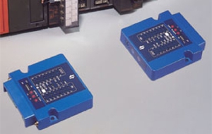
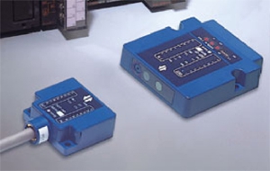
SOT-CP8/16 Series (CC-Link Support Type)
Specification
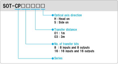
Model No. Descriptions
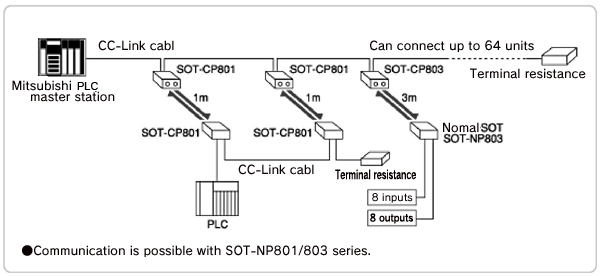
Sample System Configuration
CC-Link Specifications
|
Applicable PLC
|
MELSEC A/QnA/Q series, Mitsubishi Electric
Supports A series, QnA series, and Q series |
|
Applicable master unit
|
AJ61BT11, A1SJ1BT11, AJ61QBT11, A1SJ61QBT11, QJ61BT11
|
|
Communication method
|
Control & Communication Link (CC-Link)
|
|
No. of occupied stations
|
1
|
|
Transfer route
|
Bus
|
|
Transfer format
|
HDLC
|
|
Link connect
|
Connector terminal block (MSTB 2.5/5-ST-5.08, Phoenix Contact)
|
|
Connecting cable
|
CC-Link dedicated cable
|
|
Maximum transfer distance
|
1200 to 100m (depending on baud rate)
|
|
Transfer rate
|
10M, 5M, 2.5M, 625K or 156Kbps
|
Specifications
8bit Type
|
Model
|
SOT-CP801H
|
SOT-CP801S
|
SOT-CP803H
|
SOT-CP803S
|
|
Optical axis direction
|
Head on
|
Side on
|
Head on
|
Side on
|
|
Power voltage
|
DC24V
|
|||
|
Operating voltage
|
DC18 – 30V
|
|||
|
Current consumption
|
100mA MAX
|
|||
|
Transfer distance
|
0 to 1m (with light intensity control knob set to MAX)
|
0 to 3m (with light intensity control knob set to MAX)
|
||
|
Emitting direction
|
30 degrees or more (at 1m distance)
|
5 degrees or more (at 3m distance)
|
||
|
Transfer method
|
Half duplex
|
|||
|
Detection method
|
Continuous monitoring of bit status changes
|
|||
|
Transfer time
|
15ms max. (in M/S mode) or 20ms max. (in X mode)
|
|||
|
Sender element
|
Near infrared light emitting diode
|
|||
|
Receiver element
|
Photo-transistor
|
|||
|
No. of transfer bits
|
8 points input and 8 points output
|
|||
|
No, of control inputs
|
1 (CTL/TCD)
|
|||
|
No, of control outputs
|
1 (RCV)
|
|||
|
Indicator lamp
|
POW lamp : Lights (red) with power supply on. |
|||
|
Switches
|
1.Station No. select switches (2 rotary switches)
2.Transfer rate select switch (a rotary switch) 3. Mode select switches (dip switches) |
|||
|
Ambient operating temperature
|
-20 to 50 deg C (no condensation allowed during operation)
|
|||
|
Ambient operating humidity
|
40 – 85% RH (no condensation allowed)
|
|||
|
Ambient operating illuminance
|
4,000Lx or less (no disturbing rays should directly enter receiver)
|
|||
|
Vibration resistance
|
10 to 55Hz, 1.5mm dual amplitude 2 hours each in X, Y and Z directions
|
|||
|
Shock resistance
|
500m/s2 (approx. 50G), 2 hours each in X, Y and Z directions
|
|||
|
Enclosure rating
|
IP40
|
|||
|
Power supply connection
|
Connector terminal block (MSTB 2.5/2-ST-5.08, Phoenix Contact)
|
|||
|
Outside dimensions
|
90mm (W) × 80mm (D) × 20mm(H)
|
|||
16bit Type
|
Model
|
SOT-CP1601H
|
SOT-CP1601S
|
SOT-CP1603H
|
SOT-CP1603S
|
|
Optical axis direction
|
Head on
|
Side on
|
Head on
|
Side on
|
|
Power voltage
|
DC24V
|
|||
|
Operating voltage
|
DC18 – 30V
|
|||
|
Current consumption
|
100mA MAX
|
|||
|
Transfer distance
|
0 to 1m (with light intensity control knob set to MAX)
|
0 to 3m (with light intensity control knob set to MAX)
|
||
|
Emitting direction
|
30 degrees or more (at 1m distance)
|
5 degrees or more (at 3m distance)
|
||
|
Transfer method
|
Half duplex
|
|||
|
Detection method
|
Continuous monitoring of bit status changes
|
|||
|
Transfer time
|
15ms max. (in M/S mode) or 20ms max. (in X mode)
|
|||
|
Sender element
|
Near infrared light emitting diode
|
|||
|
Receiver element
|
Photo-transistor
|
|||
|
No. of transfer bits
|
15 (16) points input and 15 (16) points output
(16th point may be switched to control input/output) |
|||
|
No, of control inputs
|
1 (CTL/TCD) (with DSW3 off)
|
|||
|
No, of control outputs
|
1 (RCV) (with DSW3 off)
|
|||
|
Indicator lamp
|
POW lamp : Lights (red) with power supply on.
CTL/TCD lamp : Lights (red) with CTL input on. Lights (green) with TCD input on. DT/RCV lamp : Lights (red) when data is normally received. Lights (green) when during stabilized reception. IN lamp : Lights (red) with relevant optical output data on. OUT lamp : Lights (green) with relevant optical input data on. RUN lamp : Lights (green) during normal data exchange with master unit. ERR lamp : Lights (red) with data error received and turns off during normal communication. SD lamp : Lights (red) during linked data transmission. RD lamp ; Lights (red) during linked data reception. |
|||
|
Switches
|
1. Station No. select switches (2 rotary switches)
2. Transfer rate select switch (a rotary switch) 3. Mode select switches (dip switches) |
|||
|
Ambient operating temperature
|
-20 to 50 deg C (no condensation allowed during operation)
|
|||
|
Ambient operating humidity
|
40 – 85% RH (no condensation allowed)
|
|||
|
Ambient operating illuminance
|
4,000Lx or less (no disturbing rays should directly enter receiver)
|
|||
|
Vibration resistance
|
10 to 55Hz, 1.5mm dual amplitude 2 hours each in X, Y and Z directions
|
|||
|
Shock resistance
|
500m/s2 (approx. 50G), 2 hours each in X, Y and Z directions
|
|||
|
Enclosure rating
|
IP40
|
|||
|
Power supply connection
|
Connector terminal block (MSTB 2.5/2-ST-5.08, Phoenix Contact)
|
|||
|
Outside dimensions
|
90mm (W) × 80mm (D) × 20mm(H)
|
|||
Note: A separate user manual with detailed information about this type is available on request.