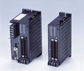
SPC-MX/SX Series
Feature
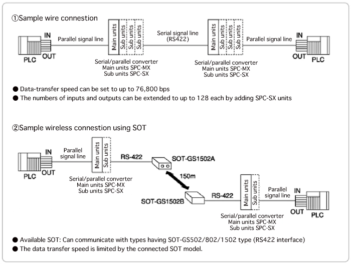
Supports RS422 interface
This is a signal transmitter capable of transmitting multiple input and output signals using a small number of signal lines. A single main unit is capable of transmitting up to 32 input signals and 32 output signals. Up to three sub-units can be added, making it possible to extend the system to up to 128 inputs and 128 inputs, adding 32 inputs/outputs at a time. Wireless signal transfer is available using our free space optical communication. The device can transfer signals directly with computers or other devices with a serial interface.
Specification
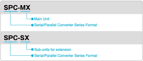
Model No. Descriptions
Sample System Configuration
Specifications
Main Unit SPC-MX
|
Power supply voltage
|
24V DC ±10% Power ripple 10% or less
|
||||||
|
Current consumption
|
100mA MAX. at 24V DC
|
||||||
|
Serial interface part
|
I/F Type
|
Compliant with RS422
|
|||||
|
I/F Signals
|
a. RD : Received data input
b. CD : Carrier detection input c. SD : Send data output d. TC : Transmission clear output |
||||||
|
Transmission method
|
Full-duplex or half-duplex bi-directional
Selectable with function setting switch |
||||||
|
Serial data format
|
a. Synchro method : Start/Stop synchronization
b. Data length : 8bit c. Start bit : 1bit d. Stop bit : 1bit e. Parity : Even number f. Assay method : Parity check and check sum |
||||||
|
Data transmission rate
|
600/1200/2400/4800/9600/19200/38400/76800 bps
Selectable with function setting switch In the wireless transmission by means of SOT, transmission rate become restricted by the transmission rate of SOT to be used. |
||||||
|
Parallel I/F part
*Exclusive of delay in response time when transmission is synchronized and parallel I/F. |
Power supply
|
To be supplied from terminal block for parallel I/F
|
|||||
|
Input signal numbers
|
32 points(It can extend up to 128 points maximum when 3 subunits are added)
|
||||||
|
Input circuit
|
Isolation method : Photo coupler insulated input (Sink type)
Rated input voltage : 12/24V DC Rated input current : Approx. 3/5mA Leakage current at OFF : 1.2mA or less (At 24V DC) *When using two wire system proximity switch, check the leakage current at OFF. Working voltage range : 10.2 to 26.4V DC (Ripple rate : 5% or less) Input resistance : Approx. 5k Ohm Delay in response time : OFF to ON 1ms Max. ON to OFF 1ms Max. |
||||||
|
Output signal numbers
|
32 outputs (It can extend up to 128 points maximum when 3 subunits are added)
|
||||||
|
Output circuit
|
Isolation method : Photo coupler insulated output (Sink type)
Emitter common (32 points/1 common) Working load voltage range : 4.5 to 30V DC Load current : 0.1A Maximum/1 point Simultaneous ON current : 1.0A Maximum/32 points Surge killer : Clamp diode Delay in response time : OFF to ON 1ms Maximum ON to OFF 1ms Maximum |
||||||
|
Transmission time
|
Transmission rate
|
Transmission method
|
Signal channel No
|
||||
|
32 points
|
64 points
|
96 points
|
128 points
|
||||
|
600 bps
|
Half-duplex
|
475 ms
|
697 ms
|
919 ms
|
1141ms
|
||
|
Full-duplex
|
327
|
475
|
623
|
771
|
|||
|
1200 bps
|
Half-duplex
|
253
|
364
|
475
|
586
|
||
|
Full-duplex
|
169
|
244
|
319
|
394
|
|||
|
2400 bps
|
Half-duplex
|
128
|
185
|
242
|
299
|
||
|
Full-duplex
|
88
|
126
|
162
|
199
|
|||
|
4800 bps
|
Half-duplex
|
72
|
101
|
130
|
159
|
||
|
Full-duplex
|
47
|
66
|
85
|
104
|
|||
|
9600 bps
|
Half-duplex
|
38.5
|
54
|
69.5
|
85
|
||
|
Full-duplex
|
28
|
37.5
|
47
|
56.5
|
|||
|
19200 bps
|
Half-duplex
|
25
|
33.5
|
42
|
50.5
|
||
|
Full-duplex
|
17.5
|
23
|
28.5
|
34
|
|||
|
38400 bps
|
Half-duplex
|
12.6
|
17.4
|
22.5
|
27
|
||
|
Full-duplex
|
7.0
|
10.5
|
14
|
17.5
|
|||
|
76800 bps
|
Half-duplex
|
10.5
|
14
|
17.5
|
21
|
||
|
Full-duplex
|
4.7
|
6.6
|
8.5
|
10.5
|
|||
|
Control I/F
|
Input signal
|
a. CTL (Control)
|
OFF : Normal operation
ON : Transmission stop Sent data +SD “H”, -SD “L” Transmission stop +TC “H”, -TC “L” Parallel output All points OFF RCV output OFF DT output OFF |
||||
|
b. TCD
(Transmission stop) |
OFF : Normal operation
ON : Transmission stop Sent data +SD “H”, -SD “L” Transmission stop +TC “H”, -TC “L” Receiving is in normal operation *Effective at full-duplex only |
||||||
|
c. M/S
(Switching between master and slave) |
OFF : Master Priority on sending
ON : Slave Priority on receiving * Effective at half-duplex only. |
||||||
|
Input circuit
|
Identical specification with parallel I/F
|
||||||
|
Output signal
|
a. RCV
(Receiving synchronization) |
Stays “ON” while receiving data from other S/P converter (Operation equal to CD signal of SOT)
|
|||||
|
b. DT (Data normal)
|
Comes ON when something is wrong such as corruption of data with the data received from other S/P converter.
When something is wrong with received data, this converter stays “OFF” before data is normal again. |
||||||
|
c. ALM
* 1. (Reception level alarm) |
Comes “OFF” when reception level of SOT to be connected lowers.
|
||||||
|
d. CDO
* 1. (Reception) |
Comes “ON” when reception level of SOT to be connected normal.
* 1. ALM and CDO output become effective when the connection of SOT-GS50/80/150 series. |
||||||
|
Output circuit
|
Identical specification with parallel I/F.
|
||||||
|
External connection
|
Serial I/F
|
D-bus connector 15-pin
XM2A-1501 (Pin connector) OMRON make or equivalent XM2S-1511 (Hood) OMRON make or equivalent |
|||||
|
Parallel I/F
|
Flat cable connector 40-pin
FCN-365P040-AU FUJITSU make or equivalent |
||||||
|
Power/control I/F
|
Terminal block 9-pole
Addition of subunit Flat cable connector 14-pin HIF3BA-14PA-2.54DS Hirose make or equivalent |
||||||
|
Power for parallel I/F
|
Terminal block 2-pole
|
||||||
|
Setting the transmission conditions
|
Addition Numbers setting switch (Rotary switch)
|
This switch allows you to set the number of subunits to be added.
|
|||||
|
Function setting switch (4bit DIP switch)
|
This switch allows you to set following functions :
a. Switching of transmission method 1 bit b. Switching of serial transmission rate 3 bits |
||||||
|
Monitor indicator lamp (Red and green LEDs)
* For I/O numbers 1 through 16 (17 through 32), I/O indication becomes 0 through 9 and A through F. |
1. Power indicator lamp (Red, green)
|
You can check the equipment status
through Power indicator lamp. POW 1 point |
|||||
|
2. Receiving indicator lamp (Red)
|
RCV 1 point
|
||||||
|
3.Serial send data indicator lamp (Red)
|
SD 1 point
|
||||||
|
4. Serial receiving data indicator lamp (Red)
|
SD 1 point
|
||||||
|
5. Parallel input indicator lamp *2
|
IN 32 points
Inputs 1 to 16 : Red LED17 to 32 : Green LED |
||||||
|
6. Parallel output indicator lamp *2
|
OUT 32 points
Outputs 1 to 16 : Red LED 17 to 32 : Green LED *2 For I/O numbers 1 through 16 (17 through 32), I/O indication becomes 0 through 9 and A through F. |
||||||
|
Weight
|
Approx. 660g (Main part)
|
||||||
|
Accessories
|
Connector for serial I/F For body side 1 set
Crossover for power Red and blue 1 each |
||||||
|
Options
|
1. Cable with connector for parallel I/F SOT-FB harness
2. Cable with connector for addition of subunit SPC-X □ harness : 1 For addition of 1 subunit : 2 For addition of 2 subunits : 3 For addition of 3 subunits |
||||||
Subunit SPC-SX
|
Power supply voltage
|
24V DC ±10% Power ripples 10% or less |
|
Current consumption
|
50mA Max. at 24V DC
|
|
Parallel I/F part
|
1. Power supply To be supplied from power terminal block for parallel I/F.
2. Input signal numbers 32 points 3. Input circuit Same specification as the mein unit SPC-MX 4. Output signal numbers 2 points 5. Output circuit Same specification as the main unit SPC-MX |
|
External connection
|
1. Parallel I/F Flat cable connector 40 pin
2. Addition of subunit Flat cable connector 14 pin 3. Power terminal block for parallel I/F : 2 poles All are the same specification as the main unit SPC-MX |
|
Setting of transmission conditions
|
Address setting switch (Rotary switch)
|
|
Monitor indicator lamp (Red and green LED)
|
1. Power supply (Red and green) : POW 1point
You can confirm the equipment status through the Power indicator lamp. *2. Parallel input indication : IN 32 points Inputs 1 through 16 : Red LED17 through 32 : Green LED *3. Parallel output indication : OUT 32 points Outputs 1 through 16 : Red LED 17 through 21 : Green LED * For I/O numbers 1 through 16 (17 through 32), I/O indication becomes 0 through 9, A through F. |
|
Weight
|
Approx. 440g (Main part)
|
|
Accessories
|
Crossover for power Red and blue 1 each
|
|
Options
|
1. Cable with connector for parallel I/F SOT-FB harness
2. Cable with connector for addition of subunit SPC-X □ harness : 1 For addition of 1 subunit : 2 For addition of 2 subunits : 3 For addition of 3 subunits *SPC-SX is unable to connect to SPC-M and SPC-M1. |
Common Specification
|
Ambient operating temperature
|
-10 to +50°C
|
|
Ambient operating humidity
|
40 to 85% RH
|
|
Vibration resistance
|
Frequency : 10 to 55Hz
1.5mm
2 hours in each of 3 directions, X, Y and Z (per JIS C0040) |
|
Shock resistance
|
500m/s2 3 cycles in each of 3 directions,
X, Y and Z (per JIS C0041) |