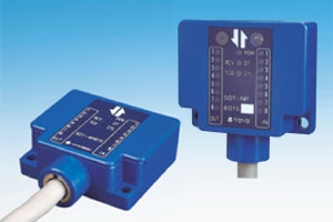
SOT-NP4/8 Series
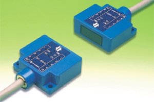
Specification
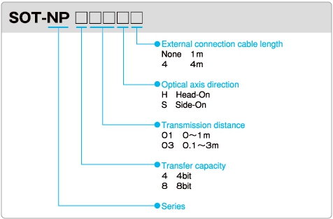
Model No. Descriptions
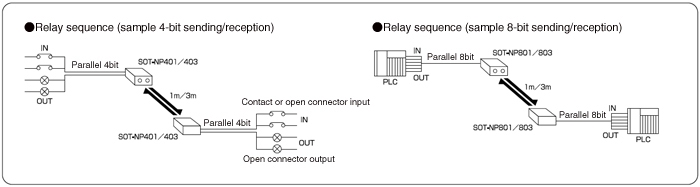
Sample System Configuration
Specifications
|
Model
|
SOT-NP401H/S□
|
SOT-NP403H/S□
|
SOT-NP801H/S□
|
SOT-NP803H/S□
|
|
Rated power voltage
|
DC12/24V Ripple 100 mVp-p or less
|
|||
|
Power voltage used
|
DC10 – 30V Ripple 100 mVp-p or less
|
|||
|
Consumable current
|
60mA MAX
|
|||
|
Transmission distance
|
0 – 1m
|
0.1 – 3m
|
0 – 1m
|
0.1 – 3m
|
|
Direction angle
|
30°
|
5° | 30° | 5° |
|
Transmitting points
|
Input 4-bit/Output 4-bit
|
Input 8-bit/Output 8-bit | ||
|
Transmission method
|
Half-duplex 2-way and 1-way direction
|
|||
|
Detecting method
|
Bit reverse any time comparison method
|
|||
|
Transmitting time
|
15ms MAX (M/S mode) 20ms MAX (X mode)
|
|||
|
Projecting element
|
Short-wave-length infrared LED
|
|||
|
Receiving element
|
Photo transistor
|
|||
|
Modulation method
|
Pulse modulation 45 KHz
|
|||
|
Input date points
|
4 points
|
8 points
|
||
|
input model Photo-coupler insulation type (Sink input)
Input signal Contact-point or Open collector Input voltage DC10 – 30V However, input voltage is the line-to-line voltage between EXT+V and IN Input current 4±0.5mA (in DC 24V) However, the residual voltage when turned On is below than 2V. The leakage current when turned Off is below than 0.5mA. |
||||
|
Output date points
|
4 points
|
8 points
|
||
|
Output model Non-insulation model Open collector output by NPN transistor (Sink Output)
Load voltage DC4.5 – 30V Load current 100mA per point The residual voltage when output turned On Should be below than 1.5V and total load current Below than 500mA |
||||
|
Indicators
|
POW display: Lights up (red) when power is on
CTL/TCD display: Lights up (red) when CTL input is on/lighted (green) when TCD input is on Lighted DT/RCV display: Lights up (red) during successful data reception/lighted (green) during stable optical reception IN display: Lights up (red) when data input is on OUT display: Lights up (green) when data output is on When the RCV display (green) is lighted , the DT display (red) will also be lighted . |
|||
|
Connection
|
With attached 1-m cable 18C × 0.14mm2 (AWG26)
With attached 1-m cable 26C × 0.14mm2(AWG26) |
|||
|
Ambient operating temperature
|
-20 – +50°C No freezing temperatures allowed.
|
|||
|
Ambient operating humidity
|
40 – 85% RH No condensation allowed.
|
|||
|
Ambient operating illumination
|
4,000lx or less for incandescent and fluorescent lamps
No externally disturbed light shall directly enter the receiver. |
|||
|
Vibration resistance
|
10 to 55Hz in frequency, 1.5mm in complex amplitude and 5minutes for sweep
20 cycles in each of X, Y and Z directions |
|||
|
Shock resistance
|
500m/s2, 20 cycles in each of X, Y and Z directions
|
|||
|
Enclosure rating
|
IP66
|
|||
|
Outside dimensions
|
60mm (W) × 50mm (D) × 22mm (H)
|
|||